Deep Bedrock Wells for Municipal Use: A Series on the Process - #4) Well Gravel Packing & Grouting
Welcome to the fourth installment in our well drilling series following the construction of Monument Well 10 by Layne, A Granite Company and Lytle Water Solutions! In the first blog we talked about how the borehole for the well is drilled. In the second blog we discussed the basics of geophysical logging and well design, and in the third blog we discussed the installation of the well casing and screen in the borehole. Now that the well has been set to total depth in the borehole, it is time to go over the process of finishing the well completion with the gravel packing and grouting process.
GRAVEL PACK
In its current state, the 12.8-inch outside diameter well casing is being held in tension at the surface inside the 20-inch open borehole; centralizers are used to keep the casing centered in the borehole, with only drilling muds between the well casing and the inside of the borehole. The space between the well casing and the borehole is called the “annular space,” and it must be filled with a material that can allow water to pass efficiently from the aquifer into the well but limit the amount of sediment from the aquifer that can get into the well. The most common material for this job is very specifically sized gravel.
The size of the gravel is determined by the grain size of the aquifer materials. The larger the grains in the aquifer, the larger the grains in the gravel pack, and the larger the slots in the well screens to allow water into the well. When the grains of sands in the aquifer are smaller, the gravel pack grain sizes and well screen slot sizing must be reduced to limit the amount of sediment that can enter the well.
For this project, LWS selected an 8-12 mesh gravel to fill the annular space, but what does 8-12 mean? Gravel is sized using mesh screens. A number 8 screen has 8 equal sized square openings per linear inch of screen, and a number 12 screen has 12 square openings per linear inch. For size reference, an average window screen has about 17 openings per linear inch. So, an 8-12 gravel is gravel that passes through a number 8 screen, but does not pass through a number 12 screen.
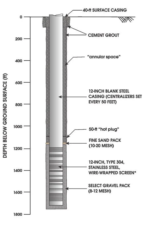
Well completion schematic.

Figure 1: Gravel pack in hopper.
Now that we understand the sizing, lets look at how the gravel is placed in the borehole. The gravel cannot simply be poured down the open borehole from the surface. It would take far too long for the gravel to settle through the drilling mud to the bottom, so the gravel is placed starting from the bottom of the hole through a “tremie pipe.” The tremie pipes are sections of small diameter threaded pipe that are installed in the annular space before the well casing was installed in one long string all the way down to near the bottom of the borehole. The 8-12 gravel is placed in a hopper and is pumped through a pipe under the hopper into the tremie pipe (see Figure 1). The hopper releases a controlled amount of gravel into the pipe which then flushes the gravel down to near the bottom of the borehole where the gravel settles through the mud a short distance to the bottom. In this way, the tremie pipe minimizes the potential for bridging of the gravel pack by maintaining a minimal distance above the settled pack. As the gravel level rises in the borehole, the tremie pipe is lowered to “tag'“ the top of the gravel pack so the drillers know the level of the gravel. When the level of the gravel nears the bottom of the tremie pipe, one section of tremie is pulled out of the hole and the process begins again.
It is important that the gravel is not fed into the tremie pipe too quickly. If too much gravel is added, the grains of gravel can “bridge” across the inside of the tremie pipe and create a blockage that is very difficult to remove, so the gravel packing is a slow and steady process.
Once the 8-12 gravel pack is within 20 feet of the top of the aquifer, the gravel packing process is halted. As the remaining gravel settles into place, the gravel pack level will continue to rise slightly, and it is very important that the gravel not come up above the top of the aquifer, as the well permit has a very specific interval that can be open to water production. The last 10 feet of the gravel pack is a much finer sand, a 20-40 mesh, that helps to create a less porous surface for the grout material to be placed.
One important aspect of setting the gravel pack is that (during this process) the drilling mud is being thinned to both facilitate the settling of the gravel pack and to help in the next major step in the well completion process, the well development (watch for next week’s blog for well development details). The drilling mud is thinned with fresh water, sodium hypochlorite, and Aqua-Clear PFD, a dispersant used to remove mud and sediment from the borehole.
GROUT
Now that the gravel pack is set, it’s time to grout. Grout is used to seal the well from the aquifers above the permitted production zones. In this case, since this is an Arapahoe aquifer that is being completed, the grout seal must be placed through the overlying Denver and Dawson aquifers. Therefore, while the borehole was drilled through three different aquifers, by law, only a single aquifer can be tapped in a well; this Arapahoe aquifer well is only permitted to produce water from the lowest of the three aquifers.
The grout seals the well from the two upper aquifers. The grout is placed in the annular space of the well using the same tremie pipe from the gravel packing process. However, the grout seal in this instance is over 1,000 feet in total depth. If you were to place 1,000 feet of liquid grout on top of the gravel pack the pressure would cause the grout to seep into the gravel pack and could cause serious problems by blocking the well screens. To help reduce that risk, only 50 feet of grout is placed at first. This 50 feet of grout is called a “hot plug” and it is allowed to fully set before the remainder of the grout is added so as to protect the gravel pack from grout infiltration.
Once the hot plug is set, the grouting moves quickly. The grout is brought in a line of concrete trucks. The first concrete truck uses the chute on the truck to deliver the grout to a pump truck, which pressurizes the grout and pumps it down the tremie pipe in the annular space to just above the hot plug. When the first concrete truck is empty, another truck begins to delivery grout to the pump truck. The tremie pipes are not pulled until the grout reaches the surface to minimize mixing between the grout and the water. If the grout is just poured down the borehole, it would dissolve in the water and be ineffective. By filling the annular space from the bottom up, the grout that mixed the most with the water is the first to come to the surface.
Once the grout reaches the surface, the pumping continues until the grout coming out of the hole at the surface has a similar consistency to the grout going into the hole. This makes it more likely that there are no pockets of poor-quality grout in the annular space. Finally, with the well fully grouted, the tremie pipes are removed from the annular space and the grout is allowed to set, undisturbed, for at least 24 hours before moving on to the development phase.

But that is where we leave the Monument Well 10 project for now. Next time we will cover the well development process, so stay tuned! And if you have a need for a water resources engineering for well drilling, groundwater modeling, water rights cases, or more, please reach out to Lytle Water Solutions and we will be happy to put together a plan for your needs. We help with projects big and small.
Bruce Lytle, President of LWS: bruce@lytlewater.com
Chris Fehn, Senior Project Engineer: chris@lytlewater.com
Anna Elgqvist, Senior Engineer: anna@lytlewater.com